


OBD2 connector pinout: 16-pin DLC explained
The OBD2 connector, also known as the Data Link Connector (DLC), is the 16-pin diagnostic socket used to connect a scan tool or vehicle interface to an OBD2-equipped vehicle.
At first glance, the connector looks simple. There are 16 possible terminal positions, so it is easy to assume that all 16 pins should always be present and perform the same job on every vehicle.
They do not.
Some terminals have standardized functions, such as battery power, ground or CAN communication. Others are used only with older diagnostic protocols, while several positions are deliberately left available for manufacturer-specific circuits.
This guide explains the complete OBD2 pinout, what the important pins actually do and what you can learn from the connector when a scanner will not power up or communicate with the vehicle.
Pin 4 = Chassis ground
Pin 5 = Signal ground
Pin 6 = CAN High
Pin 7 = K-Line
Pin 14 = CAN Low
Pin 15 = L-Line on applications that use it
Pin 16 = Battery positive
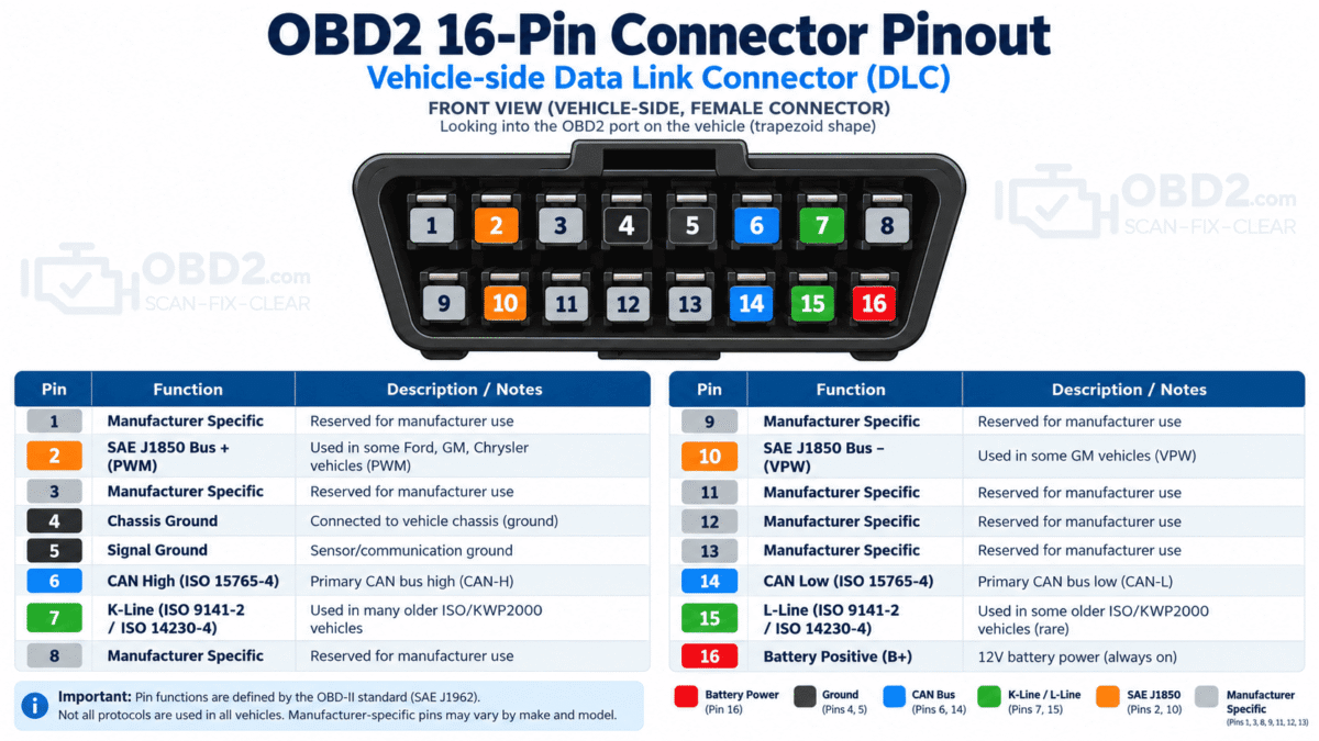
OBD2 16-pin connector diagram
When looking directly into the vehicle-side diagnostic connector, the terminals are numbered in two rows.
        VEHICLE OBD2 / DLC
     _______________________
    /  1  2  3  4  5  6  7  8
   /  9 10 11 12 13 14 15 16
   -----------------------------
Connector orientation matters. The socket may be mounted horizontally, vertically, upside down or at an angle underneath the dashboard. Before measuring voltage, resistance or continuity, confirm the pin numbering rather than relying only on the connector’s physical position.
Complete OBD2 connector pinout
| Pin | Typical function | What it means |
|---|---|---|
| 1 | Manufacturer-specific | May be unused or assigned to an OEM-specific circuit. |
| 2 | SAE J1850 Bus + | Used by some older OBD2 communication systems. |
| 3 | Manufacturer-specific | Function depends on the vehicle. |
| 4 | Chassis Ground | Ground reference connected to the vehicle chassis. |
| 5 | Signal Ground | Ground reference used by diagnostic electronics. |
| 6 | CAN High | Standard diagnostic CAN High on CAN-equipped vehicles. |
| 7 | K-Line | Used by ISO 9141-2 and ISO 14230/KWP2000 systems on many older vehicles. |
| 8 | Manufacturer-specific | May be used for an OEM-specific network or electrical function. |
| 9 | Manufacturer-specific | Function varies by vehicle. |
| 10 | SAE J1850 Bus − | Used with applicable SAE J1850 implementations. |
| 11 | Manufacturer-specific | May carry an additional OEM network. |
| 12 | Manufacturer-specific | May be used for an additional network or diagnostic circuit. |
| 13 | Manufacturer-specific | Function varies by application. |
| 14 | CAN Low | Diagnostic CAN Low, paired with pin 6. |
| 15 | L-Line | Used on some older ISO diagnostic implementations. |
| 16 | Battery Positive | Supplies vehicle battery voltage to compatible diagnostic equipment. |
What the important OBD2 pins actually do
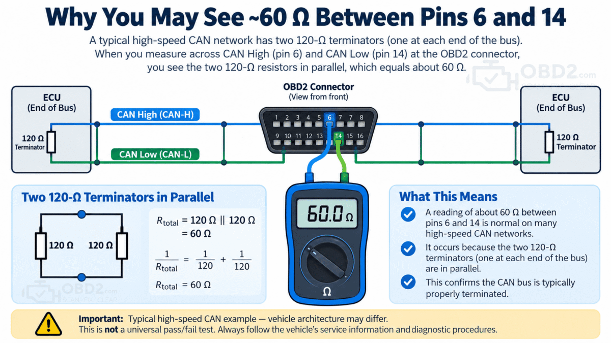
For most diagnostic work, a handful of terminals deserve most of the attention.
Pin 16 — scanner power
Pin 16 provides battery positive voltage to compatible diagnostic equipment.
On a conventional 12-volt vehicle, a measurement between pin 16 and a valid ground should normally be close to battery voltage.
This makes pin 16 one of the first places to check when a scan tool remains completely dead after being connected.
For example, imagine that the scanner works normally on another car but does not even switch on when connected to this one. Before blaming the scanner or the vehicle ECU, checking DLC power can immediately tell you whether the problem is much simpler.
A missing supply at pin 16 may be caused by:
- a blown diagnostic-port fuse;
- a fuse shared with an accessory or power outlet;
- damaged wiring;
- corrosion;
- a damaged or pushed-back terminal;
- a vehicle-specific power distribution fault.
Always confirm the vehicle wiring diagram before replacing fuses or applying power to the connector.
Pins 4 and 5 — grounds
The two standardized ground terminals are:
- Pin 4 — Chassis Ground
- Pin 5 — Signal Ground
A poor ground can create surprisingly confusing symptoms. A scanner might power up and then reset, connect intermittently or lose communication when the electrical load changes.
Simple continuity alone does not always prove that a ground is healthy. A damaged connection can still show continuity with almost no current flowing while developing excessive voltage drop under load.
Pins 6 and 14 — CAN High and CAN Low
On vehicles using CAN for standardized OBD communication:
- Pin 6 = CAN High
- Pin 14 = CAN Low
The two wires form a differential communication pair. Instead of treating each wire as an independent signal, diagnostic equipment interprets the voltage relationship between them.
These are now among the most familiar OBD2 terminals because modern vehicles predominantly use CAN-based communication.
However, seeing pins 6 and 14 in the connector does not mean that every electronic module in the vehicle sits directly on that same network. Modern vehicles may contain several CAN buses connected through one or more gateways.
Pin 7 — K-Line
Pin 7 is commonly associated with K-Line communication used by ISO 9141-2 and ISO 14230/KWP2000 systems.
These protocols were common before CAN became widespread.
This explains something that can initially look suspicious when inspecting an older car: a perfectly functional OBD2 vehicle may use pin 7 for diagnostic communication and have no terminals at pins 6 and 14.
Empty CAN positions therefore do not automatically mean that the diagnostic connector is damaged.
Pin 15 — L-Line
Pin 15 can be used as an L-Line on some older implementations, typically as part of initialization or supplementary communication.
Many vehicles do not use it at all.
Pins 2 and 10 — SAE J1850
Some older OBD2 vehicles use SAE J1850 communication.
- Pin 2 — J1850 Bus +
- Pin 10 — J1850 Bus − on systems that require it
These older communication systems should not be confused with CAN on pins 6 and 14.
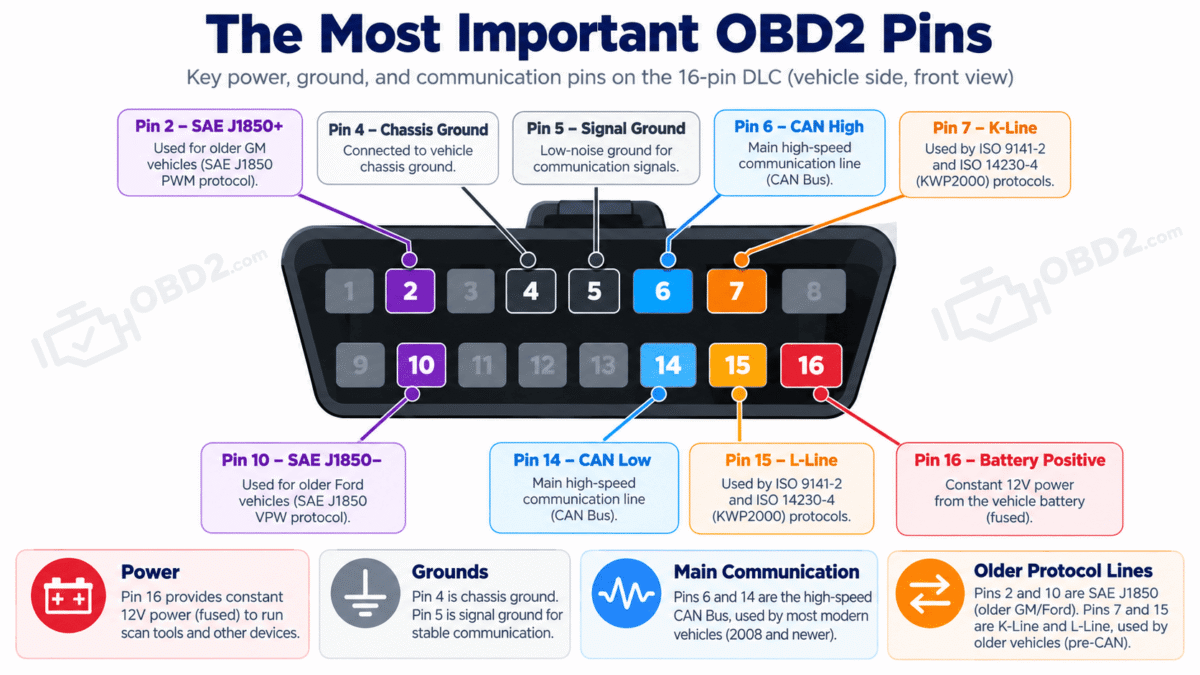
Can you measure 60 ohms between pins 6 and 14?
This is one of the most common CAN-bus checks discussed in automotive diagnostics, but it needs context.
On many conventional high-speed CAN networks, two 120-ohm termination resistors are installed at opposite ends of the network. Electrically, those two resistors in parallel produce a reading close to 60 ohms.
That is why technicians sometimes measure resistance between CAN High and CAN Low when investigating a network fault.
But approximately 60 ohms is not a universal pass/fail test for every vehicle at the OBD2 connector.
Modern architectures may include gateways, multiple CAN networks, different termination arrangements, modules that remain awake after the ignition is switched off, or diagnostic networks that are not permanently connected to every internal bus.
For this reason, resistance measurements should only be made with the circuit in the correct powered-down condition and interpreted using the diagnostic procedure for the specific vehicle.
A resistance value by itself does not tell the entire story.
Why are some OBD2 pins missing?
An OBD2 connector has 16 possible terminal positions. It does not require every position to contain a metal terminal.
The connector was designed to accommodate several standardized communication systems as well as manufacturer-defined functions. A vehicle therefore only needs the contacts required by its architecture.
A CAN-based vehicle may use pins 6 and 14. An older ISO-equipped vehicle may rely primarily on pin 7. Other positions may be reserved for additional networks or simply left empty.
That means an apparently incomplete connector can be completely normal.
Manufacturer-specific terminals
Some of the remaining positions may be used by manufacturers for functions such as:
- additional vehicle networks;
- body-control communication;
- diagnostic wake-up circuits;
- OEM-specific power or ignition signals;
- proprietary communication buses;
- special programming functions.
This is also why an unused-looking pin should never be assumed safe to ground, short or supply with battery voltage.
For any non-standard terminal, the correct reference is the wiring information for the exact vehicle.
Troubleshooting the OBD2 port
The symptoms at the scanner often tell you which part of the connector to check first.
The scanner is completely dead
Start with the basics:
- Inspect the DLC for bent, corroded or pushed-back terminals.
- Verify battery voltage at pin 16.
- Check the ground circuits at pins 4 and 5.
- Identify and test the appropriate diagnostic-port fuse.
- Check for voltage drop where appropriate rather than relying only on continuity.
- Inspect previous aftermarket wiring or accessory installations.
Do not bridge terminals or feed battery voltage into another DLC pin in an attempt to make the scanner work.
The scanner powers up but will not communicate
This changes the diagnosis considerably. If the scanner has power, the basic supply circuit is probably present, but communication still has to reach the appropriate vehicle control system.
Possible causes include:
- an unsupported or incorrectly selected protocol;
- damaged CAN or K-Line wiring;
- a gateway fault;
- a control module without power or ground;
- a wider vehicle-network fault;
- poor DLC terminal contact;
- aftermarket wiring modifications;
- a security gateway restriction;
- an incompatible diagnostic interface;
- a faulty scan tool or cable.
Several modules cannot be reached
When many modules disappear at the same time, investigate common network components, shared power supplies, grounds and gateways before assuming that several control units failed simultaneously.
Only one module cannot be reached
If the rest of the vehicle communicates correctly, the DLC itself may be working normally. Attention then shifts toward the affected module, its power and ground circuits and its connection to the network.
OBD2, CAN FD and manufacturer-specific diagnostics
The presence of a 16-pin diagnostic connector does not mean that every diagnostic operation uses basic standardized OBD2 communication.
Generic OBD2 mainly provides standardized emissions and powertrain information.
Access to systems such as ABS, airbag/SRS, electronic parking brake, body control, ADAS, transmission adaptations or injector coding often depends on manufacturer-specific diagnostic communication.
A capable multi-system scanner can access many of these modules through the same physical DLC, but the communication involved goes beyond basic generic OBD2.
The same principle applies to newer vehicle networks. Some vehicles use CAN FD or other newer communication architectures for certain functions. A basic OBD2 interface may still retrieve standardized emissions data while being unable to communicate with advanced OEM modules.
When advanced diagnostics are required, the important question is therefore not simply whether the connector fits. The interface must support the actual communication protocol and diagnostic functions used by the vehicle.
OBD2 connector vs OBD1
The standardized 16-pin connector is one of the major differences between OBD2 and the earlier OBD1 era.
Before OBD2, manufacturers frequently used their own diagnostic connectors, locations and communication methods.
Depending on the vehicle, an older diagnostic system might use:
- a proprietary connector;
- a socket in the engine compartment;
- a manufacturer-specific adapter;
- a blink-code procedure instead of a conventional scanner.
This is one of the reasons OBD2 made general diagnostic equipment much more practical: a common physical interface could now be used across many different vehicle brands.
Safety when testing an OBD2 connector
The DLC provides direct access to vehicle power and communication circuits. Incorrect probing can turn a diagnostic problem into an electrical problem.
Basic precautions include:
- confirm the pin numbering before testing;
- use suitable high-impedance measuring equipment;
- never intentionally short communication terminals together;
- never apply battery voltage to a data pin;
- do not measure resistance on a powered circuit;
- check manufacturer wiring information before testing OEM-specific terminals;
- use suitable breakout equipment for advanced network diagnosis.
For routine fault-code reading, none of this electrical probing is normally necessary. These tests become relevant when the diagnostic connector itself or the vehicle network is suspected of causing a communication problem.
OBD2 pinout FAQ
Which pin powers an OBD2 scanner?
Pin 16 is the standardized battery-positive terminal used to supply compatible diagnostic equipment.
Which pins are ground?
Pin 4 is chassis ground and pin 5 is signal ground.
Which pins are CAN High and CAN Low?
For standardized diagnostic CAN communication, pin 6 is CAN High and pin 14 is CAN Low.
Is it normal for some OBD2 pins to be missing?
Yes. Many terminal positions are optional, protocol-dependent or available for manufacturer-specific use.
Why does my scanner have power but no communication?
Power at the connector only confirms part of the circuit. Communication problems may involve the network wiring, gateway, modules, protocol compatibility, connector terminals or the diagnostic interface itself.
Technical references
The physical diagnostic connector, its functional requirements and contact allocation are defined through the SAE J1962 diagnostic connector standard.
- SAE J1962 — Diagnostic Connector
- Volkswagen technical information — DLC pin assignment
- Infiniti technical information — DLC and CAN testing
If your scanner is already communicating and you have retrieved a fault code, use our OBD2 DTC Code Library to identify its meaning.
